Analog Filter with Gain and Subtraction
The Quarto can be used to filter analog signals. In this tutorial, we will take two analog inputs, , and and create a new output defined by the following equation:
Finally, we will low-pass filter this signal with a cut-off frequency of 10 kHz. We will output the unfiltered signal on DAC channel 1 and the filtered signal on DAC channel 2.
Setup
We will fully utilize the 1 mega-sample per second (MS/s) capability of the Quarto and have it measure two analog channels at 500 kHz each. This means each channel will make a measurement every 2 µs. That is configured in the setup function:
void setup() {
  configureADC(1,2,0,BIPOLAR_5V,getADC1); // Have ADC1 take measurement every 2 µs, ±5 V range
  configureADC(2,2,1,BIPOLAR_5V,getADC2); // Have ADC2 take measurement every 2 µs, ±5 V range
}
In this case, both ADC channels are set to the ±5 V range.
Main Functions
When ADC1 gets its measurement, we need to wait until ADC2 gets its measurement as well before we can proceed, so we will just store the result in a global variable adc1 . Then when ADC2 gets its measurement, we can do the subtraction and amplification. So the two callback functions getADC1 and getADC2 that we configured in the setup will become:
double adc1; // global to store latest adc1 value

double b = 1.15; // scaling on the second channel
double c = 3.75; // scaling on subtracted signal

void getADC1() {
  adc1 = readADC1_from_ISR(); //store ADC1 voltage measurement
}

void getADC2() {
  double adc2 = readADC2_from_ISR(); //store ADC2 voltage measurement
  double pre_filter = (adc1 - adc2 * a ) * b;
  writeDAC(1,pre_filter); //write value to DAC1
}
Now we have implemented as defined above by doing a weighted subtraction between ADC channel 1 and channel 2 and then multiplying the result by b. The next step is to apply the low-pass filter to this result.
The Digital Filter
:::tip Overview Only Digital filtering is a complex topic, and this example is only going to give an intuitive explanation and will not go into the theory. For reference, the filter we are implementing is a first-order infinite impulse filter (IIR) and we will use it to approximate a first-order analog R-C filter. :::
To low-pass filter the signal, we want to stop it from changing too quickly, and to do this we want to limit how much a new ADC measurement can affect the output. The simplest way to do this is have:
where is between 0 (exclusive) and 1. The smaller is, the less influenced the Output is by the Input. The problem with this is that while the is less influenced from fast changes in the , it is also less influenced by all changes from the , regardless of the frequency of that change. We want a unity filter where for slow signals, the equals the , so we need to add back the low-frequency gain lost from the attenuation caused by . We will add this gain back by adding a term that anchors the to its previous value, .
Now when the Input suddenly changes, the will only change by an amount set by the factor . That increase, however, will cause the to increase, which will then cause to increase. Which will cause to increase. Which will cause to increase, and so on and so on. To determine the final (or steady-state) value of , we set = since is no longer changing. Then the above equation becomes
And we see that the equals the . The coefficient determins how fast the gets to the value. A low means it takes along time for to change from a change in the , while an near 1 would cause to very quickly match any change in the . This filter is a good approximation of an analog low-pass R-C filter. Now that we have the basic filter, we can implement it by adding just a single line to our getADC2 function (and defining analog_output as a global):
double analog_output; //global to store analog output for filtering

void getADC2() {
  double adc2 = readADC2_from_ISR(); //store ADC2 voltage measurement
  double pre_filter = (adc1 - adc2 * b ) * c;
  analog_output = a * pre_filter + (1-a) * analog_output;
  writeDAC(1,pre_filter); //write value to DAC1
  writeDAC(2,analog_output); //write value to DAC2
}
where a is a constant between 0 and 1 that we need to define.
Setting α
We won't cover the derivation here. But for the filter implemented above, the following equations can be used to relate the value of to the filter cut-off frequency () and the sampling interval ():
In this example, , . So and .
It's worth looking at the limits of these equations. As the cut-off frequency approaches 0, then y approaches zero as does . This makes sense as at very low cut-off frequencies, the output should barely change to new data, so should be very small. In the other direction when is 1, the filter is doing nothing as the filter output is simply equal to the input. Working backwards this means that must not be greater than 1. That restriction means y must not be greater than 1. Finally, for y to be 1 or less, the argument to tan must be or less. Solving for the cut-off frequency we get that the maximum value for is . Put another way, the maximum cut-off frequency is one-quarter the samping frequency. In our case, we sample every 2µs or 500kHz, so the highest filter frequency is 125 kHz. And really the filter needs to be below 125 kHz, since at 125 kHz, is 1, so there is no filter.
Combining the upper and lower limits, we get:
and if this condition it met, then will be between 0 and 1.
Code
Putting this altogether, we have:
double adc1; // global to store latest adc1 value

double analog_output; //global to store analog output for filtering
double a = 0.11838; // 10kHz filter

double b = 1.15; // scaling on the second channel
double c = 3.75; // scaling on subtracted signal

void setup() {
  configureADC(1,2,0,BIPOLAR_5V,getADC1); // Have ADC1 take measurement every 2us, ±5V range
  configureADC(2,2,1,BIPOLAR_5V,getADC2); // Have ADC2 take measurement every 2us, ±5V range
}

void getADC1() {
  adc1 = readADC1_from_ISR(); //store ADC1 voltage measurement
}

void getADC2() {
  double adc2 = readADC2_from_ISR(); //store ADC2 voltage measurement
  double pre_filter = (adc1 - adc2 * b ) * c;
  analog_output = a * pre_filter + (1-a) * analog_output;
  writeDAC(1,pre_filter); //write value to DAC1
  writeDAC(2,analog_output); //write value to DAC2
}
Data
Using this code, if we send a triangle wave into ADC 1 (yellow) and a square wave into ADC 2 (cyan), then we get the following output:
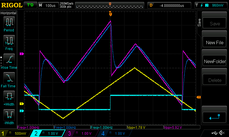
where DAC 1 is the unfiltered output (magenta) and DAC 2 has the filtered output (blue).
Adjustable Settings
The above code has the values of a, b and c fixed. But we can make this variables adjustable via qCommand. Additionally, but using smartData, we can have a control for the filter frequency and get alpha to be calculated automatically. To make the variables b and c adjustable, we need to add the following:
#include "qCommand.h" // include qCommand library

qCommand qC; //instatiate the qCommand object

void setup() {
  configureADC(1,2,0,BIPOLAR_5V,getADC1); // no change
  configureADC(2,2,1,BIPOLAR_5V,getADC2); // no change
  qC.assignVariable("b", &b); // assign the variable b to the string "b"
  qC.assignVariable("c", &c);  // assign the variable c to the string "c"
}
void loop() {
  qC.readBinary(); // for qCommand, listen to binary commands
  qC.readSerial(Serial); // listen to command on main serial port
  qC.readSerial(Serial2); // list on secondary serial port
}
Finally, will create a new smartData object for the filter frequency. Whenever this value changes, we will recalculate alpha. This is done with the following code:
SmartData<double> FilterFreq = 10; //set in units of kHz

void setup() {
  qC.assignVariable("FilterFreq", &FilterFreq);
  qC.assignVariable("Alpha", &alpha, true); // set Alpha as read-only for qControl
  FilterFreq.setLimits(0, 125); // restrict filter to between 0 and 125kHz
  FilterFreq.runOnUpdate(calcAlpha);
}

void calcAlpha(void) {
  double y = tan(PI * 2e-6 * FilterFreq * 1e3); // 1e3 to put FilterFreq from kHz to Hz
  a = 2*y / (y + 1);
}
Combining all this yields the full code:
#include "qCommand.h" // include lib

double b = 1.15; // scaling on the second channel
double c = 3.75; // scaling on subtracted signal

double analog_output; //global to store analog output for filtering
double a; // filter value to be calculated lataer
double adc1; // global to store latest adc1 value

qCommand qC;
SmartData<double> FilterFreq = 10; //set in units of kHz

void setup() {
  configureADC(1,2,0,BIPOLAR_5V,getADC1); // Have ADC1 take measurement every 2us, ±5V range
  configureADC(2,2,1,BIPOLAR_5V,getADC2); // Have ADC2 take measurement every 2us, ±5V range
  qC.assignVariable("b", &b); //
  qC.assignVariable("c", &c);
  qC.assignVariable("Filter Frequency", &FilterFreq);
  qC.assignVariable("Alpha", &a, true); // set Alpha as read-only for qControl
  FilterFreq.setLimits(0, 125); // restrict filter to between 0 and 125kHz
  FilterFreq.runOnUpdate(calcAlpha);
  calcAlpha(); // run once to set at start
}

void calcAlpha(void) {
  double y = tan(PI * 2e-6 * FilterFreq * 1e3); // 1e3 to put FilterFreq from kHz to Hz
  a = 2*y / (y + 1); //set alpha
}

void loop() {
  qC.readBinary();
  qC.readSerial(Serial);
  qC.readSerial(Serial2);
}

void getADC1() {
  adc1 = readADC1_from_ISR(); //store ADC1 voltage measurement
}

void getADC2() {
  double adc2 = readADC2_from_ISR(); //store ADC2 voltage measurement
  double pre_filter = (adc1 - adc2 * b ) * c;
  analog_output = a * pre_filter + (1-a) * analog_output;
  writeDAC(1,pre_filter); //write value to DAC1
  writeDAC(2,analog_output); //write value to DAC2
}
With this, the scaling for b and c and the filter frequency can be adjusted dynamically via either the serial commands or via qControl.